Components Required
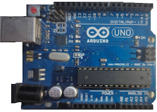
- Arduino Uno:
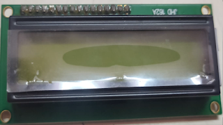
- 16x2 LCD Display:
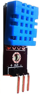
- DHT11 Sensor
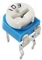
- 10K Preset
DHT-11 module
This module is used to measure humidity and temperature of surrounding. It comprises a thermistor and a capacitive humidity plates to measure temperature and humidity.
Features
- Temperature Range: 0°C to 50°C (±2°C accuracy)
- Humidity Range: 20% to 90% RH (±5% accuracy)
- Operating Voltage: 3V – 5V
- Current Consumption: ~2.5mA (during measurement)
- Sampling Rate: 1 reading per second (1 Hz)
- Interface: Single-wire digital output (not analog)
Pinouts
- 1. + or VCC → Power supply (3.3V – 5V)
- 2. DATA → Digital signal output
- 3. - or GND → Ground
DHT11 connection with Arduino
- 1. Connect + terminal of DHT-11 to 5volts of Arduino.
- 2. Connect - terminal of DHT-11 to GND of Arduino.
- 3. Connect OUT terminal of DHT-11 to A0 pin of Arduino.
About 16x2 LCD Display
The name "16x2 LCD display" comes from the fact that it has 16 columns and 2 rows, meaning we can display 32 characters on this screen. Characters can be alphabets, numbers, or custom-made characters. Each column is made from a 5x8 matrix of pixels (40 pixels per column).
- Operating voltage: 4.7V to 5.3V
- Current consumption: 1mA without backlight
- Alphanumeric display: can show alphabets and numbers
- Works in both 8-bit and 4-bit mode
- Available in Green and Blue backlight
Pinouts
- 1. Vss: Connect to GND
- 2. Vdd: +5V (4.7V–5.3V)
- 3. VEE: Contrast adjustment
- 4. RS: Command/data register
- 5. R/W: Normally GND (write mode)
- 6. Enable: Activates read/write
- 7. Data bit 0:- To microcontroller to send 8 bit data
- 8. Data bit 1:- To microcontroller to send 8 bit data
- 9. Data bit 2:- To microcontroller to send 8 bit data
- 10. Data bit 3:- To microcontroller to send 8 bit data
- 11. Data bit 4:- To microcontroller to send 4/8 bit data
- 12. Data bit 5:- To microcontroller to send 4/8 bit data
- 13. Data bit 6:- To microcontroller to send 4/8 bit data
- 14. Data bit 7:- To microcontroller to send 4/8 bit data
- 15. LED+: Backlight
- 16. LED-: Backlight
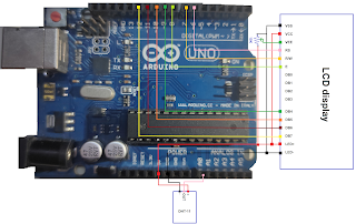
16x2 LCD conenction with Arduino
- 1. VSS and LED- pin of LCD are combined together and are grounded.
- 2. VCC and LED+ pin of LCD are combined together and is connected to 5v pin of Arduino.
- 3. Then connect a Preset to VEE to adjust the contrast of LCD by varying the knob of Preset.
- 4. Then connect RS pin of LCD to 6th pin of Arduino and R/W pin of LCD to 7th pin of Arduino.
- 5. Then connect E pin of LCD to 8th pin of Arduino.
- 6. Then connect DB4 pin of LCD to 9th pin of Arduino, DB5 pin to 10th pin , DB6 pin to 11th pin and DB7 to 12th pin of Arduino.
- 7. Connect 1 terminal of toggle switch to 5 V and it's other terminal to A0 pin.
Circuit Diagram
Arduino Code
#include <LiquidCrystal.h >
#include "DHT.h"
DHT dht(A0, DHT11);
LiquidCrystal lcd(6,7,8,9,10,11,12);
float humidity,celcius,fahrenheit;
void setup()
{
lcd.begin(16,2);
dht.begin();
}
void loop()
{
delay(2000);
lcd.clear();
humidity = dht.readHumidity();
celcius = dht.readTemperature();
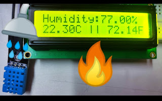
lcd.print("Humidity:");
lcd.print(humidity);
lcd.print("%");
lcd.setCursor(0,1);
lcd.print(celcius);
lcd.print("C || ");
fahrenheit=1.8*celcius + 32;
lcd.print(fahrenheit);
lcd.print("F");
}